Rancilio Silvia mods
The Rancilio Silvia is a frequently bought espresso machine for home use. Several versions of the machine have been produced, with different boilers, steam wands etc. After some time, my Silvia suddenly started boiling the water in the water reservoir. After some googling around, this appeared to be caused by a defective over pressure valve (OPV). This led to some upgrades, listed below.
OPV replacement and manometer installation
Early versions of the Silvia had a fixed OPV, meaning the brew pressure could not be adjusted by the operator. Later versions came with an adjustable OPV, meaning the operator can adjust the pressure required to open the valve.
When the pressure reaches the valve setting (either fixed, or adjusted), excess pressure/steam is released back into the water reservoir. When the OPV is broken, the valve may release pressure too early, resulting in either poor pressure when steaming/brewing, or too much pressure returning to the water reservoir—effectively boiling the water in the reservoir. The latter was the problem with mine.
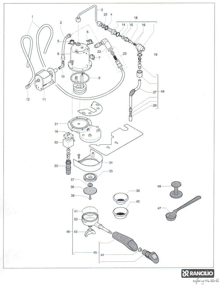
On Silvia machines, the OPV is either attached directly to the boiler (part #59 here), or to the boiler with a male to male coupler (part #22 here). Since the replacement OPV is adjustable, a pressure gauge is required to properly set the OPV. Two options exist:
- A manometer attached to the portafilter, or
- A manometer installed permanently in the machine's plumbing.
Since a manometer fits nicely on the front panel of the machine, I decided to go with this approach.
Since the coupling between the pump hose and the OPV is known to leak after OPV replacement, getting the "braided hose" to replace the old teflon hose is a nice upgrade. That gives the following upgrades:
- OPV replacement (see Stefano tutorial for removing the valve here). Note that in order to get the correct angle on the OPV, several copper washers may be required. Originally, there is only one copper washer on either side of the male-male connector between OPV and boiler, but multiple washers may be used if necessary.
- Braided hose installation. This simply involves removing the old teflon hose, which must be removed when removing the OPV anyways, and replacing it with the new braided hose.
- Manometer installation. To install a manometer, a new pipe branch must be added so the pressure at the manometer maches the rest of the system. Additionally, for best results, a hole must be drilled in a panel on the machine to make the meter visible.
Several ways to fit the manometer to the pipe system on the silvia exist. Avi suggests to add the manometer at the hose from boiler to steam valve. Instead, since the OPV was to be removed anyways, I placed a male tee fitting between the boiler and the OPV, replacing the male to male coupler next to part #22 here. The tee fitting is of type BSP with Parallel threads (BSPP) with all male ends of size 1/4", and may be obtained online for 5$. This effectively makes a new pipe branch for attaching a manometer. The La Marzocco copy manometers (and similar) fit the 1/4" BSP threads. These meters may be obtained for around 40$.
Fitting the new OPV++
After replacing the OPV, replacing the teflon hose with the braided one, and attaching the BSPP tee, the machine looks like this inside:


The OPV is fitted to the BSPP tee, where the manometer is attached to the top output of the tee.
The newer version of the braided hose comes with an integrated 90 degree bend and fits directly to the pump. Since my local shop didn't have this in stock, I got the old version with a separate bend, which requires teflon tape to avoid leaks at either side of the pipe bend.
Fitting manometer in front panel
Finally, to make the manometer visible to operator, a hole must be drilled in the front panel or side panel of the machine.


A 40mm hole saw attached to a drill press was used to make the hole for fitting the manometer
The vertical center of the hole is centered below the on/off button and light, while the hole is horizontally placed so that the lower end is slightly higher than the bottom of the brew button cutout and slightly lower than the bottom of the steam valve cutout.

Manometer fitted in front panel.
Steam wand replacement
After having used the Rancilio Pro X at work for some time, it was tempting to upgrade to the newer steam wand for the Silvia. This wand has an improved joint, which should make it more flexible to use and maneuver in different directions.
However, to my disappointment, using the new steam wand feels more awkward, as it is slightly bigger and therefore requires entering the mug with more care. Therefore, I cannot recommend spending nearly 100$ on a new steam wand...


New steam wand with "nice" ball joint attached
The new steam wand unit can be used with the old knob
PID control and web interface using ESP32
The Silvia uses mechanical thermostats to control boiler temperature. In normal brew mode, the brew thermostat cycles the heating element on/off around its setpoint. When you flip the steam switch, the machine switches to a higher-temperature control path for steaming. In addition, the Silvia has one or more safety thermostats/thermal cutouts that trip on overtemperature and must be reset (depending on model).
This thermostat-based control is effectively bang-bang control (on/off with hysteresis), which causes noticeable temperature cycling. That cycling is one reason people “temperature surf” the Silvia. A PID controller reduces the cycling by driving the heater in shorter bursts (time-proportional control), keeping the boiler temperature closer to a target.
Commercial PID kits exist, but they’re often closed and can take up space. A compact, reversible DIY approach can be built using:
- Microcontroller like ESP32 for control and web UI.
- AC solid-state relay (SSR) to switch power to the boiler heating element. Even though the heater current is only a few amps (e.g., ~1100 W at 220–240 V for many EU machines), SSRs should be derated heavily—a common choice is a 25 A (or higher) zero-cross AC SSR mounted to metal for heat sinking. Note: many of the SSRs sold on ebay etc are copies of more expensive counterparts and may not live up to expectations. I have a feeling the one I bought is a copy, but it works without extreme heat production so far:)
- Temperature sensor + matching interface, e.g.
- K-type thermocouple + MAX31855/MAX6675 (SPI), or
- PT100 RTD + an RTD interface board
- Wires/cables that are rated for ish 100 degrees celcius (at least the wires close to the boiler).
Wiring diagrams for people who dont understand normal circuit drawings

The illustration above shows the stock Silvia wire layout (left), and the modified Silvia (right). Each cable in the illustration has (roughly) the same colour as the original cable. Conceptually, the PID/ESP32 does not switch the boiler current directly. Instead, the ESP32 outputs a low-voltage control signal to the SSR input, and the SSR’s mains side acts like an electronically controlled switch in series with the heating element. In the simplest brew-only PID setup, the SSR is wired so that its output replaces the brew thermostat contacts: the two wires that originally went to the brew thermostat are moved to the SSR’s output terminals. This can be observed in the illustration above, where the modified Silvia has no cables connected to the brew thermostat.
If you also want PID-controlled steam temperature, a common approach is to treat the steam switch as a mode input (brew setpoint vs steam setpoint) rather than relying purely on the original steam thermostat. I may do this soon!


Above, the image to the left shows how the cables are connected in the stock Silvia. To the right, the female cable connectors previously connected to the brew thermostat are now connected to wires connected to the SSR.


Left: the microcontroller (esp32) with MAX31855 breakout is positioned by the pump. Right: The SSR is attached behind the lower front panel. Two holes were drilled through the frame to fasten the SSR to the frame. Since the frame acts as a heat sink, an external heat sink has not been necessary for me (yet).
PID control code/setup
The code for the ESP32 to make PID work is available at github.